Beaglebot – A BeagleBoard based robot

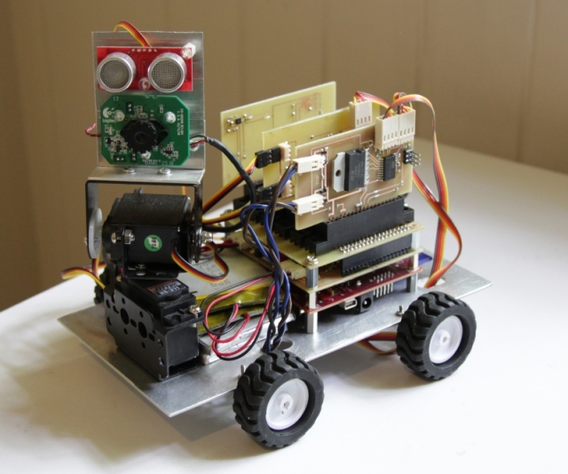
Over the last 6 months or so I’ve been working on a BeagleBoard based robot. The motivation for this was to build a general robotics platform to try out some ideas I have on Simultaneous Localization and Mapping (SLAM) and robust sensor fusion. Here’s the result so far:

As you can probably tell from the photo, I’m a computer programmer, not a mechanical engineer!

The main features are:

Software

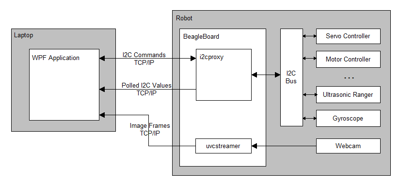
Here’s the overall architecture of the system:

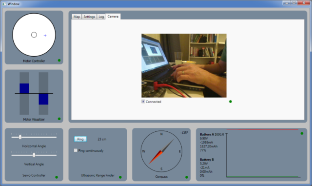
The robot is controlled from a WPF application running on a laptop, which communicates with the robot over an 802.11n wireless network.  Here’s a screenshot of the app:

Most of the peripherals on the robot are accessed over the I2C bus, via a C program called i2cproxy. i2cproxy runs on the BeagleBoard and listens on a given port. It responds to simple text commands, for example, ‘get 30 10’ (get the value at i2c address 30, register 10), or ‘set 30 10 2’ (set address 30, register 10 to the value 2). It also supports burst reads (reading from multiple registers in a single I2C transaction), and automatic polling of I2C registers. The source code for i2cproxy is available here.

The WPF application on the laptop communicates with i2cproxy on the BeagleBoard via the I2CBus class. Here’s some sample code using this class (this code runs on the laptop, and accesses the I2C bus on the BeagleBoard):

// Open the channel.
var bus = new I2CBus();
bus.CommandPort = 2000;
bus.PollPort = 2001;
bus.Connect();

// Get the value at address 30, register 10.
var value = bus.Get(30, 10);

// Set the value of address 30, register 10, to value 2.
bus.Set(30, 10, 2);

// Poll address 30, registers 10-15, every 1000ms.
bus.AddPoll(1000, 30, 10, 6, MyPollCallback, null);

The BeagleBoard itself runs Ubuntu 11 with a patched 3.1.0 kernel. The root file system was generated with rootstock. I had previously been using Angstrom, however I ran into driver and network issues which were mostly resolved when I switched to Ubuntu.

Video Streaming

There are plenty of ways to get a webcam video stream off the BeagleBoard. Two good examples are mjpeg-streamer and gstreamer:

mjpeg-streamer lets you stream video from a UVC webcam as an MJPEG sequence over HTTP (MJPEG is essentially a sequence of JPEG images with the JPEG DHT segment omitted). Its relatively small so you can build it on the BeagleBoard itself and avoid the hassles of cross-compilation (though you will need your kernel headers and the libjpeg8 package). Here’s an example command-line:

./mjpg_streamer -i plugins/input_uvc/input_uvc.so -o "plugins/output_http/output_http.so -p 5000"

You can view the resulting video stream in Chrome or Firefox by typing:

 http://192.168.0.70:5000/?action=stream

into your address bar (obviously change the IP).

gstreamer is incredibly flexible, and lets you do almost anything, provided you can work out the appropriate command-line incantation. Here’s a command line which transmits JPEG encoded frames over TCP/IP:

gst-launch v4l2src ! video/x-raw-yuv,width=320,height=240,framerate=\(fraction\)5/1 ! ffmpegcolorspace ! jpegenc ! multipartmux ! tcpserversink port=5000

This requires the ‘gstreamer0.10-plugins-good’ package. You can view the video stream on another machine using VLC media player. Open VLC, got to Media->Open Network Stream, and type in ‘tcp://192.168.0.70’, and you should be up and running.

Lossless Video Streaming

I’m planning to run the video stream through a set of image processing algorithms on the laptop. To do this effectively the transmitted image frames can’t have compression artifacts introduced by lossy compression codecs, like MJPEG or MPEG, as they’re likely to cause issues with the image processing. I need either a lossless codec, or to transmit the raw frames.

I tried a few lossless codecs without much success:

  • I tried PNG encoding frames in gstreamer, however I couldn’t get this to transmit a stream of images (it seems to stall the gstreamer pipeline after encoding a single image).
  • The ffmpeg gstreamer package has a lossless video codec, ffenc_ffv1. Unfortunately this completely saturated the BeagleBoard’s CPU (see here for a review of other lossless video codecs).
  • I also tried JPEG encoding the frames with maximum quality, which doesn’t produce any human visible artifacts (though they still may be visible to the image processing algorithms). This results in CPU usage of around 55% with a 320×200 image at 15fps, which is still too high.

Lossless video compression tends not to compress particularly well anyway (perhaps a ratio of 2:1) so I ended up writing a small C application, uvcstreamer, which just transmits the raw image frames over TCP/IP. My webcam (a Logitech C600) outputs frames natively in YUYV pixel format which has a down-sampled chroma channel, which reduces the frame size by 25% anyway.  Here’s the source code for uvcstreamer.

The image stream is received on the laptop and converted to a System.Drawing.Bitmap suitable for display in the WPF application by the Camera class.

Mainboard

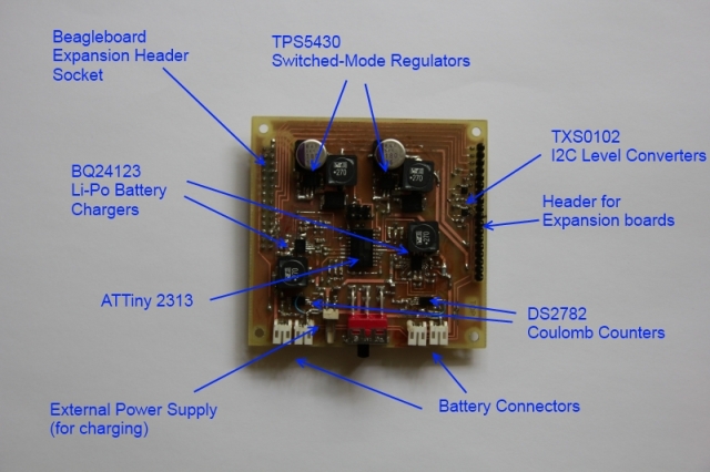
The mainboard is responsible for supplying regulated power to the BeagleBoard, motors and expansion boards, level converting the BeagleBoard’s 1.8V I2C bus to 3.3V and 5V, and managing battery charging. The board is home-made using the photo-resist method.

Initially I used a single power supply for the BeagleBoard and DC motors, however the DC motors drew to much current on start up, occasionally dropping the system voltage to the point where the BeagleBoard would reset, hence the dual power supply setup.

As described here, I’ve used switched mode regulators, rather than simple linear regulators. Switched mode regulators have a lot more external components, but can function at 95% efficiency, which makes a huge difference to battery life and heat output (a linear regulator would get 60% efficiency in the same situation).

The mainboard also includes two BQ24123 charger ICs (one for each channel). These can supply up to 2A, so they’re able to supply enough current to simultaneously charge the batteries and run the robot. Unfortunately these ICs come in a QFN package which is a bastard to solder.

The microcontroller in the center of the board is used to manage the charging, and expose the current charge state over the I2C bus. A couple of DS2782 coulomb counter ICs are also used to keep track of the voltage, current and charge remaining. The eventual plan is to have the robot autonomously find a charging station and charge itself when the battery is running low (note the ‘eventual’).

Motor Controller

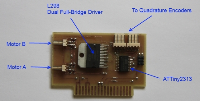
The motor controller is pretty simple: it uses an ATTiny2313 microcontroller to generate a PWM signal which is used to drive the L298 IC. The L298 contains two H-Bridges which drive the motors. The microcontroller exposes the motor state and speed through a set of I2C registers.

The microcontroller uses a modified version of Donald Blake’s TWI/I2C code (I’ve modified the original code to be register-based, and to support burst-reading). The modified I2C slave code is here.

One motor on each side of the robot is also equipped with a Pololu quadrature encoder for keeping track of wheel rotations. The output from the quadrature encoders is fed into the microcontroller and exposed over I2C (though I haven’t got the code for this running yet).

Electrical noise from the motors was initially a big problem, causing the microcontrollers to occasionally spontaneously reset. This was fixed by adding some capacitors across the motor terminals, as described here.

Motor Controller Source Code (An AVR Studio/GCC project)

Servo Controller

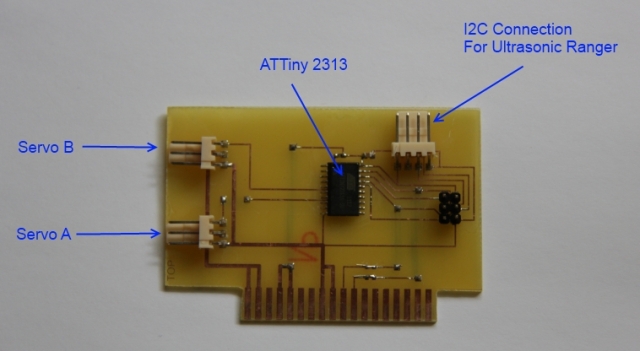
Servos are easy to control with a microcontroller – have a look at this page for a quick description of the type of control signals a servo is expecting. The ATTiny2313 has a 16 bit timer with 2 output compare units (one for each servo) which makes generating the appropriate signals pretty easy (it can be done completely in hardware). The servos are controlled by a set of I2C registers.

Servo Controller Source Code (An AVR Studio/GCC project)

IMU Expansion Board

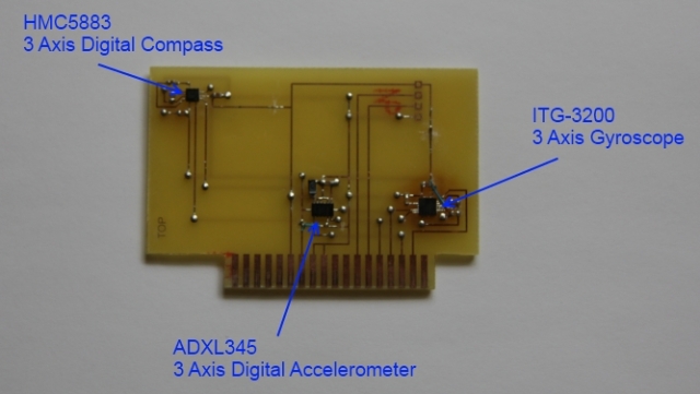
This expansion board contains an HMC5882 digital compass, and ADXL345 accelerometer, and an ITG-3200 gyroscope (all 3 axis). All 3 ICs use the I2C bus.

I’m still working on the code to sample, filter, and integrate the various values. I’ve got a prototype up and running which uses a dedicated interrupt line for each IC which is used to notify the BeagleBoard when a new sample is ready to be read (this should result in more efficient and accurate sampling than polling). The interrupt is passed through to userspace on the BeagleBoard via the gpio_keys driver. Using expansion header pins as interrupts also requires changing the mux settings. I’ll post this code when its up and running.

Thanks for reading!

Posted in BeagleBoard, Electronics, I2C, Linux, Microcontrollers, Uncategorized | Tagged , , , , , | 23 Comments

Changing the BeagleBoard I2C Bus Frequency

The stock kernel runs the I2C bus exposed on the BeagleBoard’s expansion header (bus 2) at 400KHz  (‘Fast’ mode). This is fine for most I2C slaves, however it seems to be too fast for slaves running on ATTiny and ATMega microcontrollers, even when running with an 8MHz clock. For me this was resulting in intermittent bus lock-ups when attempting to access the slave.

The I2C bus speed is set in the kernel in /arch/arm/mach-omap2/board-omap3beagle.c on this line:

omap_register_i2c_bus(2, 400, beagle_i2c2_boardinfo, ARRAY_SIZE(beagle_i2c2_boardinfo));

A bus speed of 100KHz seems to work reliably with the ATTiny2313. If you’re using Ubuntu you can use the instructions at the end of this article to rebuild a BeagleBoard-specific kernel.

Posted in BeagleBoard, I2C, Microcontrollers, Uncategorized | Tagged , , , | 1 Comment

Installing Ubuntu (Natty) on the BeagleBoard with RootStock

There are prebuilt Ubuntu images suitable for the BeagleBoard, however if you want more control over what’s included in your filesystem, and your kernel, RootStock is a good option. RootStock will assemble a complete Ubuntu file system, a kernel image and initial ramdisk based on the set of packages you provide on the command line.

Running Rootstock

There seems to be a bug in rootstock under Ubuntu 11 in that if you install it using the usual ‘apt-get install rootstock’, rootstock fails later on with a lot of:

...
bin/chown: changing ownership of `/proc/923/task/965': Operation not permitted
...

However if you just install the source code it seems to run correctly:

apt-get source rootstock
apt-get install qemu-kvm-extras
apt-get install debootstrap
cd rootstock*

Before running rootstock you need to choose which kernel version you want to run. A helpful guy over at http://rcn-ee.net has precompiled a lot of different kernel versions with the appropriate config and patches for the BeagleBoard. I’ve been using the 3.1.0 kernel. If you want to build your own kernel there are instructions at the end of this article.

Once you’ve chosen a kernel, find the URL of the corresponding image under http://rcn-ee.net/deb/natty/. Run rootstock, customizing the seed packages and kernel image URL arguments as necessary:

./rootstock --fqdn beagle --login someusername --password somepassword \
--imagesize 4G \
--seed linux-firmware,build-essential,apt,usbutils,wireless-tools,i2c-tools,wpasupplicant \
--dist natty \
--serial ttyO2 \
--kernel-image http://rcn-ee.net/deb/natty/v3.1.0-x1/linux-image-3.1.0-x1_1.0natty_armel.deb

This will (eventually) generate a couple of files: armel-rootfs-<date>.tgz which contains the root file system, and vmlinuz-<date> which is the compressed kernel.

Preparing the SD Card

Before we can boot the beagle from this we need to generate the uImage and uInitrd files for the boot partition:

sudo apt-get install u-boot-tools
mkimage -A arm -O linux -T kernel -C none -a 0x80008000 -e 0x80008000 -n "Linux" -d ./vmlinuz* ./uImage
mkimage -A arm -O linux -T ramdisk -C none -a 0 -e 0 -n initramfs -d ./initrd.img-* ./uInitrd

Copy MLO, and the generated uImage and uInitrd files to the boot partition of your SD card. If you haven’t partitioned your SD card yet, you can find instructions here. Once this is done, delete everything in the main partition, and extract the tarball produced by rootstock into it:

tar xfp armel-rootfs-*.tgz -C /media/main

Booting the BeagleBoard

Insert the SD card into your beagle and turn it on. If you’re lucky this may boot straight away. If not, you may need to change the config in U-Boot. I use the following bootcmd and bootargs (make sure you grab a copy of your settings with ‘printenv’ before running these below, as they will override your settings):

setenv bootcmd 'mmc rescan;fatload mmc 0 0x80000000 uImage;fatload mmc 0 0x81600000 uInitrd;bootm 0x80000000 0x81600000'
setenv bootargs 'console=ttyO2,115200n8 root=/dev/mmcblk0p2 rootwait ro vram=${vram} omapfb.mode=dvi:${dvimode} fixrtc buddy=${buddy} mpurate=${mpurate}'
boot

I’m using U-Boot 2011.06, so you may need a slightly different syntax if you have a different version.

Compiling your own Kernel

If you want to build your own kernel (eg to lower the I2C bus frequency), you can make the job a bit easier with a set of scripts made by the same guy who provided the precompiled kernel images earlier:

git clone git://github.com/RobertCNelson/stable-kernel.git

Edit the file system.sh.sample. If you’re going to cross-compile the kernel (recommended – compiling the kernel on the BeagleBoard will take an awfully long time), uncomment the following lines and save the file as system.sh:

...
#sudo apt-get install gcc-arm-linux-gnueabi
...
#CC=arm-linux-gnueabi-
...
#ZRELADDR=0x80008000
...

When you’re done, run:

./build_deb.sh

This will take a while, and when done will produce a file called deploy/linux-image-<version>cross_armel.deb. Put this up on a web server and you can reference it in the –kernel-image argument to rootstock above.

Posted in BeagleBoard, Linux | Tagged , , | 8 Comments

Hot-Air Soldering QFN packages


QFN (Quad Flat No leads) packages are the devil’s work. As the name implies there are no leads, just tiny pads on the bottom of the chip where it’s almost impossible to get a soldering iron or test probe to. 

I found a couple of posts which suggest you can solder these bad boys with a soldering iron by positioning the chip, then ‘floating’ solder along the PCB trace to make the connection under the chip (with help from a lot of flux). I was able to use this technique to fix a broken connection, but not for the entire chip. This also doesn’t work if you need solder on the center pad.

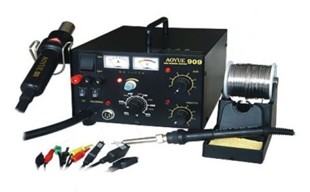
A relatively easy way to solder these at home is with a hot air station. I’m using an Aoyue 909:

Here’s the process I use:

  1. On a scrap piece of circuit board work out what distance you need to hold the hot air gun from the circuit board and for how long before the solder melts. For my setup (an Aoyue Int 909) with air temperature and flow speed set at 50%, this was holding the gun 1 inch from the PCB  for 30 seconds.
  2. Apply flux to the PCB and tin each PCB pad, including the center. Its difficult to know how much solder to apply: too much and you’ll get shorts between pads, not enough and you’ll get bad connections. I aim for a very slight dome of solder. Make sure you have a particularly small amount on the center pad, as that is prone to shorting. If you’re etching your own board its also worth decreasing the size of the center pad on the PCB to reduce the probability of center pad bridges.
  3. Apply flux to the chip and tin the chip’s pads. Make sure every pad has small amount of solder on it – this makes it much more likely that you’ll get a good connection later. Be careful not to get too much on the center.
  4. Apply plenty of flux to the PCB, and position the chip.
  5. Apply heat with the air gun using the parameters you worked out earlier (1 inch and 30 seconds for me). Move the air gun in small circles to make sure the heat is applied evenly. The chip may move around with the air flow, so tap it back into position with the tweezers as necessary (or reduce the airflow). Note that you’re supposed to follow the manufacturer’s soldering thermal profile (usually 2 minutes at a low temperature to allow the internal parts of the chip to expand with the heat, followed by 30 seconds at a high temperature to melt the solder). This is worth doing if you have a thermocouple to measure the temperature near the chip (otherwise you risk frying the chip or the PCB, as I’ve done a couple of times).
  6. When the solder melts, tap the chip into position. Its important to tap down on the top of the chip a few times – this should cause the chip to snap into position because of the solder surface tension.
  7. When its cooled, check for shorts with a multimeter. If you’ve got a short, use the air gun to remove the chip, use desoldering braid to remove the solder, and try again. The first time I tried this it took me 4 attempts to get it working without shorts (amazingly the chip still worked).
  8. Check the connections visually. If you see a suspicious looking connection you can use your soldering iron and some flux to ‘float’ solder along the PCB trace into the join.

Here’s the finished product, a BQ24123 Lithium Battery Charger:

Posted in Electronics | Tagged , , , , | 1 Comment

Switched Mode Power Supply for the BeagleBoard

I had a couple of options to consider when creating a power supply for my BeagleBoard based robot: a simple linear voltage regulator (eg the LM7805) or a fancy switched mode power supply.

Normally I’d go straight for the linear voltage regulator (I’m lazy), however this wasn’t necessarily the right choice for a couple of reasons:

  • The power consumption of my robot is relatively high (around 1 amp – see below), which can cause difficulties for a linear power regulator, and
  • I’m operating on batteries so making efficient use of the limited power I have is important.

Some requirements: the robot is powered by two LiPo cells in series which output 8.4V fully charged, and this needs to be stepped down to 5V. The power supply will need to supply at least 1 Amp, preferably more. This breaks down as:

  • 350mA for the BeagleBoard,
  • 200mA for a webcam,
  • 200mA for an ASUS N10 802.11n wireless dongle,
  • 50mA for a couple of quadrature encoders,
  • 200mA for some other sensors and microcontrollers.

Motors and servos run on a seperate power supply.

The Linear Voltage Regulator Option

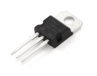
An LM7805 linear voltage regulator

Linear voltage regulators are extremely easy to use but can be quite inefficient, particularly at high currents, as they work by converting the excess voltage into heat.

The amount of heat produced is equal to (VOUT – VIN) * I. With the requirements above, the heat output is (8.4V – 5.0V) * 1.0A = 3.4 Watts. According to the LM7805’s data sheet, the device’s operating temperature will increase by 65°C per Watt, which gives us an operating temperature of 3.4W * 64°C/W + 20°C = 241°C (assuming 20°C room temperature) which puts us way over the maximum operating temperature of 125°C.

This could be overcome with a suitable heatsink, however all of that heat is chewing up a lot of battery power. The efficiency of the regulator is approximately VOUT/VIN * 100 = (5V / 8.4V) * 100 = 60%. Since the battery life of the robot is already quite limited (I’m using 2000mAH cells), 60% efficiency isn’t exactly ideal.

The Switched Mode Regulator Option

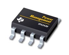
A TPS5430 switched mode regulator

Switched Mode Regulators have an efficiency in the range of 85% to 95%, potentially increasing the battery life of the robot by (95-60) / 60 = 58%. They work by generating a high frequency Pulse Width Modulation signal (between 100kHz and 1.2MHz, depending on the device) and running it through a filter to generate a constant DC output voltage. The regulator IC monitors the output voltage and modifies the duty cycle of the PWM signal to achieve the desired output voltage. All this comes at a price:

  • They require quite a few external components compared to a linear voltage regulator.
  • The circuit takes up quite a bit of PCB real estate.
  • Some of the external components mentioned in the datasheets can be quite hard to get hold of (in Australia, anyway). The output filter requires a high current inductor, and a high capacity, low ESR capacitor.
  • Because of the high currents and frequencies generated, you have to be quite careful with your PCB layout, minimizing some of the trace lengths.

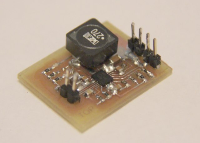
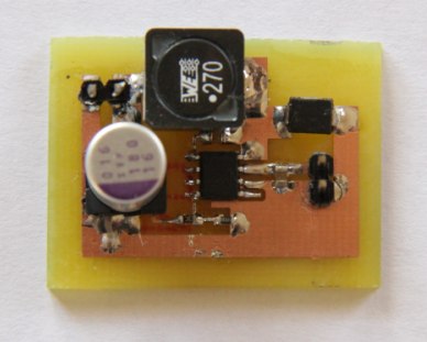
Still, it’s hard to argue with a 58% improvement in battery life. Luckily you can cheat – Dimension Engineering offer a switched mode regulator which is a drop in replacement for an LM7805. I’ve tried one of these and they work well, however I wanted to see if I could make one myself. Here’s a photo of my prototype:

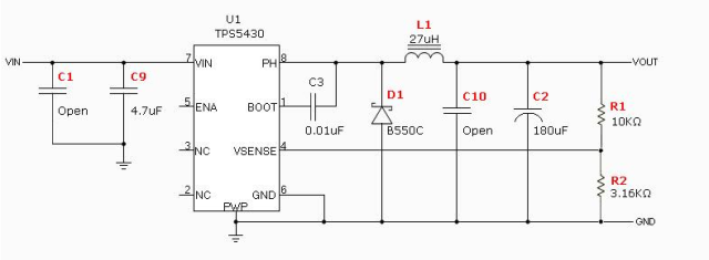
I’ve used a TPS5430 which will support up to 3 amps. It’s surface mount, but has a 0.1″ pin pitch which is very easy to solder. Texas Instruments have an online tool, SwitcherPro (free registration required) which will generate a circuit for you given a desired input and output voltage range and maximum current. Here’s the circuit generated by SwitcherPro corresponding to the prototype above:

(I have no idea what they mean by ‘open’ as the value for some of the capacitors – I’ve assumed it means they’re not necessary, and my prototype seems to work fine).

The circuit will step down 6.5V – 20V down to 5V with 92% efficiency at 1 amp, and support up to 3 amps.

Posted in BeagleBoard, Electronics, Uncategorized | Tagged , , | Leave a comment

Interfacing the BeagleBoard with an ATtiny85 Microcontroller over I2C

The next part of my project involves connecting a dozen or so sensors and actuators to the BeagleBoard, ideally in a modular, extensible way. The obvious way to do this is use some  microcontrollers, and interface them with the BeagleBoard over I2C.

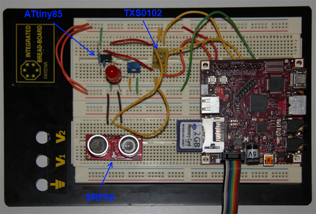
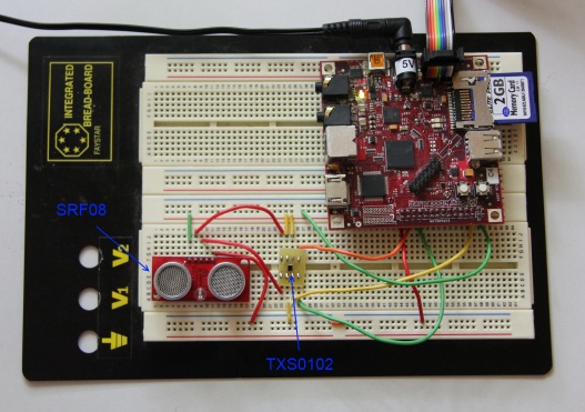
In the obligatory breadboard photo below I’ve got an ATtiny85 microcontroller with an LED hooked up to pin 2 (to test writing to an I2C register), a variable voltage divider hooked up to pin 3 (to test reading an ADC value from an I2C register), and a second I2C slave, the SRF08, just to make sure there were no issues with multiple slaves on the same bus.

Behold the breadboard:

There’s two complications:

  • The I2C bus exposed on the BeagleBoard runs at 1.8V not the usual 3-5V a microcontroller can cope with.
  • The I2C protocol isn’t trivial to implement in a microcontroller, particularly if you want to make it interrupt driven.

I’ve discussed the level translation issue previously in this post. Unfortunately I couldn’t find an easy way of doing it without using surface mount ICs. Luckily surface mount isn’t as hard as I’d expected (you can see my first surface mount PCB in the photo above, labeled TXS0102). I’m about as clumsy as it gets, so if I can solder a 0.5mm pitch IC, anyone can.

Implementing the I2C protocol on an Atmel micrcontroller is made a lot easier by some code written by Donald Blake from avrfreaks.net (based on Atmel application note AVR312). Note that this code will only work on microcontrollers with Universal Serial Interface (USI) hardware.

While Donald’s code is fantastic, it uses a byte-stream abstraction which hides some of the features of I2C I wanted to use (essentially it exposes the I2C bus as two way byte stream, much like a serial bus).  Rather than thinking of I2C as a stream of bytes, it makes more sense to me to think of it as a sequence of read and write operations on a set of registers – this is the way most sensors and actuators actually use I2C.

While it is possible to build this abstraction on top of the byte stream abstraction, this approach seemed a bit fragile for a couple of reasons:

  • The byte stream abstraction hides the I2C start and stop sequences, so client code can’t tell which bytes belong to which I2C transaction – its all just a stream of bytes. This seems a bit dangerous: if things got slightly out of step, bytes would queue up in the internal buffer, and be sent back in response to the wrong requests, and it may never get back into step.
  • There didn’t seem to be a clean way of handling reading and writing to the same register (a register would have to be exclusively read or exclusively write).

The upshot of all of this was that I modified the code slightly to make it register based. Here’s some demo client code which illustrates how to use the library:

// Callback function triggered when the slave receives a read request from the master.
uint8_t i2cReadFromRegister(uint8_t reg){
  switch (reg) {
    case 0:  return VERSION;
    case 1:  return adcRead();
    default: return 0xff;
  }
}

// Callback function triggered when the slave receives a write request from the master.
void i2cWriteToRegister(uint8_t reg, uint8_t value){
  switch (reg)  {
    case 0: i2cReg0 = value; break;
    case 1: i2cReg1 = value; break;
  }
}
int main() {
  ...
  usiTwiSlaveInit(I2C_SLAVE_ADDR, i2cReadFromRegister, i2cWriteToRegister);
  ...
}

When the library detects a read or write request from the i2c master, it calls the appropriate callback function.  The callback code then determines what to return to the master, or how to store the value just written by the master.

One thing to be aware of is that the i2cReadFromRegister and i2cWriteToRegister callback functions are both called in interrupt context, so you’ll want to keep those functions fast if you care about keeping your I2C bus and the rest of the microcontroller code running smoothly (my example above of calling adcRead() is a perfect example of what not to do). You can download the code from here (its an AVR Studio project for AVR GCC).

As described in the SRF08 I2C post, the easiest way to manipulate the I2C bus on the BeagleBoard is using the i2ctools package. Here’s the result of running i2cdetect on the above setup:

root@beagleboard:~# i2cdetect -r 2
WARNING! This program can confuse your I2C bus, cause data loss and worse!
I will probe file /dev/i2c-2 using read byte commands.
I will probe address range 0x03-0x77.
Continue? [Y/n]
     0  1  2  3  4  5  6  7  8  9  a  b  c  d  e  f
00:          -- -- -- -- -- -- -- -- -- -- -- -- --
10: -- -- -- -- -- -- -- -- -- -- -- -- -- -- -- --
20: -- -- -- -- -- -- 26 -- -- -- -- -- -- -- -- --
30: -- -- -- -- -- -- -- -- -- -- -- -- UU -- -- --
40: -- -- -- -- -- -- -- -- -- -- -- -- -- -- -- --
50: -- -- -- -- -- -- -- -- -- -- -- -- -- -- -- --
60: -- -- -- -- -- -- -- -- -- -- -- -- -- -- -- --
70: 70 -- -- -- -- -- -- --

The 70 in the bottom left is the SRF08, and the 26 is the microcontroller. The UU indicates that i2cdetect believes the address is in use by a system driver, so it didn’t poll the address (no idea what driver it is yet).

To get the values from I2C registers use i2cget. With the demo code I2C register 0 contains a constant (0x0A), and register 1 contains the ADC value, as determined by the position of the variable resistor. Here’s the i2cget output:

root@beagleboard:~# i2cget -y 2 0x26 0
0x0a
root@beagleboard:~# i2cget -y 2 0x26 1
0xc0

We can write values to the I2C registers using i2cset. The demo code is a bit daft: it lights the LED on pin 2 if the values stored in register 2 and 3 are the same. Initially the LED is lit, because both registers default to 0.

root@beagleboard:~# i2cset -y 2 0x26 2 10
[LED pin goes low, because the registers are now different]
root@beagleboard:~# i2cset -y 2 0x26 3 10
[LED pin goes high again]

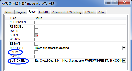
One last thing to look out for is that you will need to have a clock rate greater than 1MHz to support 100KHz I2C. On the ATtiny85, the easiest way to do this is to set the internal oscilator at 8MHz (the factory default, I think), and turn off the 8x clock prescaler (the CKDIV8 fuse):

Posted in BeagleBoard, Electronics, I2C, Microcontrollers | Tagged , , , , , | 4 Comments

Programming an ATtiny85 Microcontroller with the AVRISP mkII

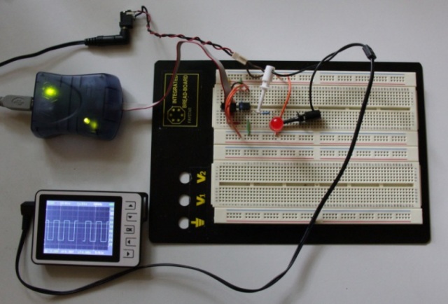
The ATtiny85 is an 8 pin microcontroller, complete with 8KB of flash, and 512 bytes of EEPROM and SRAM. It also has some hardware support for I2C (otherwise known as TWI), which makes it ideal for my current project. Here it is hooked up to Atmel’s AVRISP mkII programmer (the blue box on the top left):

The rest of the post details the steps required to get it up and running with a simple program (mostly for my benefit, as no doubt I’ll forget in a few months). Here’s what I did:

  1. Install AVR Studio 4
    Download AVR Studio 4, the latest service pack, and the AVR Toolchain Installer from Atmel: http://www.atmel.com/dyn/products/tools_card.asp?tool_id=2725. Make sure that you don’t install it under c:\Program Files (x86)\ (or any path with a bracket in the name) as you’ll get this obscure error when you attempt to build: 

    make: Interrupt/Exception caught (code = 0xc00000fd, addr = 0x4217b3)
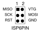
  2. Identify the pins in the AVRISP cable
    The cable pinout for the AVRISP mkII is:Pin1 is on the same side of the connector as the red stripe, and opposite where the cable enters the connector body (ie in the diagram above, the cable would be entering from the right).
  3. Wire up the microcontroller
    Wiring up the microcontroller to the programmer is pretty straightforward. Here’s the pinout for the ATtiny 85/45/25:
    Some gotchas: 

    • You will need to power the circuit with an external power supply, as  the programmer doesn’t supply power to the microcontroller.
    • You should set the microcontroller’s reset pin high. Make sure you don’t use anything less than a 4.7K resistor or the programmer may not be able to set it low to put the microcontroller into programming mode.
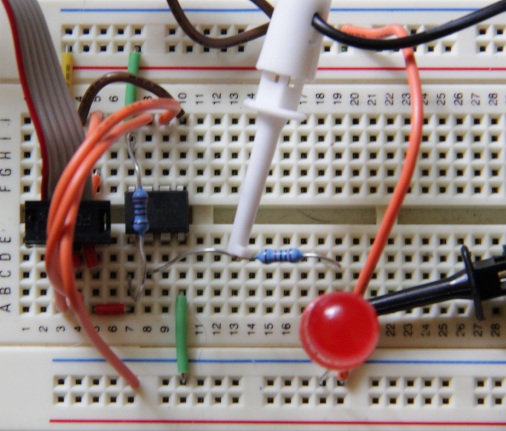
    • Make sure you connect VTG to your VCC. Without this, the programmer assumes the circuit isn’t powered.

    Here’s a closeup of the breadboard:

  4. Create a project in AVR Studio 4
    Creating a new project is easy: 

    • Hit the New Project button (or choose Project Wizard from the Project menu).
    • Choose ‘AVR GCC’ and give the project a name.
    • Choose ‘AVR Simulator 2’ and your microcontroller type.
    • Write your program.

    Here’s the program I used (it flashes an LED on pin 2):

    #define F_CPU 1000000UL
    #include <avr/io.h>
    #include <util/delay_basic.h>
    #define LED PB3
    void delay_ms(uint16_t ms){
      while (ms > 0) {
        _delay_loop_2(F_CPU/4000);
        ms--;
      }
    }
    int main(void) {
      // Set Pin 2 (PB3) as an output pin.
      DDRB |= 1 << LED;
      while(1) {
    
        // Set pin 2 high.
        PORTB |= 1 << LED;
        delay_ms(1000);
        // Set pin 2 low.
        PORTB &= ~(1 << LED);
        delay_ms(1000);
      }
      return 0;
    }
  5. Flash the Program to the Microcontroller
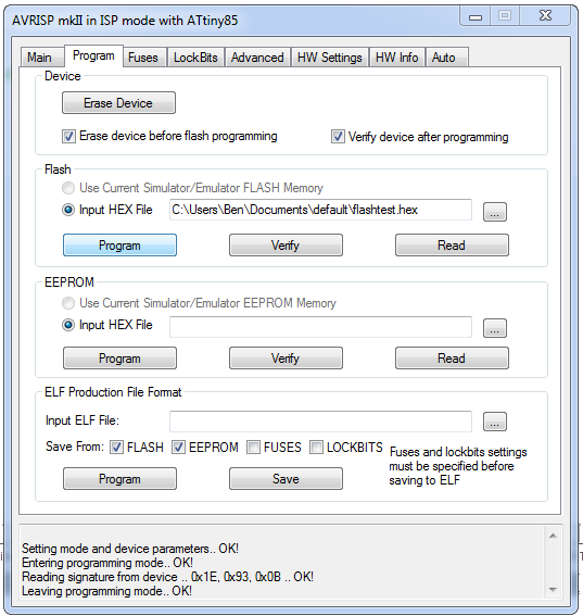
    The last step. Plug in your programmer, hit the  button on the toolbar, chose AVRISP mkII and all going well you’ll have two green LEDs lit in your programmer. If not, have a look at the AVRISP mkII programmer, page 25 for some troubleshooting hints.To flash the program to your micrcontroller, ensure you’ve built the program, switch to the Program tab in the dialog box, hit the ‘Program’ button in the ‘Flash’ panel, select your .hex file (it should be in the ‘default’ directory inside the directory which contains your .c file), and you should be done! 

Posted in Electronics, Microcontrollers | Tagged , , , | 4 Comments

Interfacing the BeagleBoard with an SRF08 Ultrasonic Ranger over I2C

The SRF08 is an ultrasonic ranger with a 3cm-6m range, and an I2C interface. It’s fairly straightforward to hook it up to a BeagleBoard using the I2C bus exposed on pins 23 and 24 of the expansion header (see page 96 of the BeagleBoard manual for the expansion header pin-out).

Here it is on the breadboard:

Level Translation

The one complication with this is that the BeagleBoard’s I2C interface runs at 1.8V, and the SRF08’s runs at 5V. If the I2C lines were uni-directional, this wouldn’t be too much of a problem as you could just use a voltage divider or transistor to handle the voltage step, but unfortunately the I2C lines are bi-directional (meaning both the master and slave are allowed to change the voltage level on the line).

A clever chap from Philips wrote an application note on how to achieve bi-directional level translation with a single MOSFET. I was able to get this to work with one of the BSN20 MOSFETs recommended in the application note, but I couldn’t get it to translate from 1.8V to 5V. The best I could do was around 2.5V to 5V which makes sense if you look at the ID to VGS chart in the BSN20’s data sheet (Figure 6).

There’s quite a few ICs which handle 2 channel, open-collector, bi-directional level translation. Some examples I found were:

Unfortunately all of them appear to be surface mount, so unless you’re able to work with surface mount components, you’re options may be limited. Luckily surface mount wasn’t as hard as I thought. I chose the TXS0102, as the BeagleBoard uses this itself, and also it was the only one I could get in Australia that didn’t require me to get a second mortgage to pay for the shipping.

The circuit itself is easy to setup, so I won’t include the schematic here. If you’re using the TXS0102 make sure you set the OE pin to high, or you’ll get some obscure error messages when you attempt to read or write to the bus. The TXS0102 also includes a 10K pull-up resistor for each channel, so no need to add your own.

Accessing the I2C Bus on the BeagleBoard

The i2ctools package contains a number of utilities which give you access to the I2C bus from the command line. On a BeagleBoard running Angstrom (and with a network connection) you can install this package with:

opkg install i2c-tools

Once you’re all wired up, you can scan the I2C bus with i2cdetect:

root@beagleboard:~# i2cdetect -r 2
WARNING! This program can confuse your I2C bus, cause data loss and worse!
I will probe file /dev/i2c-2 using read byte commands.
I will probe address range 0x03-0x77.Continue? [Y/n]
     0  1  2  3  4  5  6  7  8  9  a  b  c  d  e  f
00:          [ 4275.681945] i2c_omap i2c_omap.2: controller timed out
-- [ 4275.725128] i2c_omap i2c_omap.2: Arbitration lost
-- [ 4276.744659] i2c_omap i2c_omap.2: controller timed out
-- [ 4276.788116] i2c_omap i2c_omap.2: Arbitration lost
-- [ 4276.828186] i2c_omap i2c_omap.2: Arbitration lost
-- [ 4276.868103] i2c_omap i2c_omap.2: Arbitration lost
-- [ 4277.885101] i2c_omap i2c_omap.2: controller timed out

These errors are what I got the first time, and indicates that something is wrong with your circuit – most likely that your missing the pull-up resistors (or you’re not connected properly to the IC if it has built-in pull-up resistors). I’m guessing that the i2c driver is waiting for SCL to go high, which isn’t happening because of the lack of a pull-up resistor, so it just times out. Once you have this sorted you should get a result like:

root@beagleboard:~# i2cdetect -r 2
WARNING! This program can confuse your I2C bus, cause data loss and worse!
I will probe file /dev/i2c-2 using read byte commands.
I will probe address range 0x03-0x77.
Continue? [Y/n]    
     0  1  2  3  4  5  6  7  8  9  a  b  c  d  e  f
00:          -- -- -- -- -- -- -- -- -- -- -- -- --
10: -- -- -- -- -- -- -- -- -- -- -- -- -- -- -- --
20: -- -- -- -- -- -- -- -- -- -- -- -- -- -- -- --
30: -- -- -- -- -- -- -- -- -- -- -- -- UU -- -- --
40: -- -- -- -- -- -- -- -- -- -- -- -- -- -- -- --
50: -- -- -- -- -- -- -- -- -- -- -- -- -- -- -- --
60: -- -- -- -- -- -- -- -- -- -- -- -- -- -- -- --
70: 70 -- -- -- -- -- -- --

The 70 in the bottom left is the SRF08. Slightly confusingly, the SRF08 datasheet reports the I2C address as 0xE0. This is because the least significant bit in an I2C address is used to indicate whether it is a read (1) or write (0) address, so sometimes this bit is left off when reporting addreses. 0x70 << 1 == 0xe0.

Once we’ve got the device showing up in i2cdetect, the rest is easy. To initiate a ping use:

root@beagleboard:~# i2cset 2 112 0 81
WARNING! This program can confuse your I2C bus, cause data loss and worse!
I will write to device file /dev/i2c-2, chip address 0x70, data address 0x00, data 0x51, mode byte.
Continue?

This will trigger an ultrasonic ping, and cause the LED on the back of the module to flash briefly. You can retrieve the distance by querying the values in registers 2 and 3 (the high and low order bytes of the result, respectively):

root@beagleboard:~# i2cget 2 112 2
WARNING! This program can confuse your I2C bus, cause data loss and worse!
I will read from device file /dev/i2c-2, chip address 0x70, data address 0x02, using read byte data.
Continue? [Y/n]
0x00
root@beagleboard:~# i2cget 2 112 3
WARNING! This program can confuse your I2C bus, cause data loss and worse!
I will read from device file /dev/i2c-2, chip address 0x70, data address 0x03, using read byte data.
Continue? [Y/n]
0x3b

So here the result is 0x003b=59 centimeters. All pretty easy if you can get the level translation issue sorted.

Posted in BeagleBoard, Electronics, I2C | Tagged , , | 7 Comments

Surface Mount Soldering Made Easy(ish)

I’ve been playing around with electronics for a while, making do with my trusty breadboard for prototypes, and occasionally some veroboard if I wanted something more permanent. Unfortunately times are changing, and fewer and fewer interesting components are being made available in breadboard-friendly DIP packages (I blame Apple for convincing everyone that all electronic gadgets should be the size of a credit card).

This had been frustrating me for a while, but came to a head on my latest project where I needed an I2C level converter. Despite many wasted afternoons scouring octopart, digikey and mouser I came up empty handed, so decided it was about time I figured out this surface mount thing.

As it turned out, it was all pretty straightforward, though I did have to buy quite a lot of new equipment. Here’s my first surface mount PCB (a 0.5mm pitch DCU to DIP adapter for a TXS0102):

It’s worth pointing out that you don’t have to go the full PCB etching route like I did. Sparkfun have a number of adapter boards which break out surface mount packages to DIP. These look great for a quick prototype, but I’d been meaning to try PCB manufacturing for a while, so I thought I’d give it a go.

There’s a couple of popular ways to go about making your own PCBs. The first, and cheapest is the toner transfer method. This involves printing your circuit onto photo paper with a laser printer, then transferring the toner directly to your PCB using heat and pressure. The toner can then be used as a normal acid resist. The method sounds good however there are a lot of reports of people having mixed success, and it looks like it requires a lot of experimentation to find the right combination of laser printer, paper, and transfer method.

The second method is the standard photo sensitive resist technique. This is more expensive, but potentially more reliable, which sounded good to me. Here’s the steps I went through to create my first surface mount PCB:

  1. Create the PCB image.
    Eagle is a schematic editor which is free for non-commercial use (though it does feel a bit like 1997). Sparkfun have a good tutorial on using it which is worth checking out. To create the final image, just use File -> Export…-> Image, rather than generating the gerber files as described in the tutorial. Here’s my image:
    I created four copies of the board layout so I could experiment with different exposure times in a later step.Getting hold of land patterns can be difficult for some components. The ‘smd-ipc.lbr’ library which comes with Eagle has many standard patterns. Sparkfun also have their own Eagle library which you can download from here. Failing those options, you can manually create the land pattern if you can find a datasheet which describes it (which is what I ended up doing for the TXS0102).
  2. Print it onto acetate or polyester
    The Kinsten website claims that a sheet of translucent polyester gives better contrast than transparent acetate because the polyester absorbs more of the ink than the acetate. I used the polyester sheets and got good results with tracks 0.2mm wide, and I suspect it would probably go even smaller. I had the misfortune to only own an ink jet printer (Canon MP600) and despite trying a bunch of different printer settings I couldn’t get a high contrast image (basically the ink wouldn’t dry), so I ended up trekking down to the local print shop and using their fancy laser printer.

    Update 4/3/12: I bought a Samsung Ml-1865 monochrome laser printer from Office Works for about $70, which works well.

  3. Expose the photo-sensitive PCB
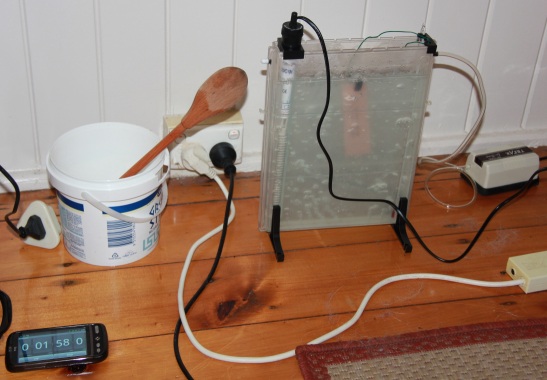
    UV exposure boxes are pretty expensive, however I found a relatively cheap one at Kinsten (product code ALT-UV). Oddly enough, the packaging indicated it was actually a UV finger nail drying machine. It also came with 3 x 15 watt UV tubes which are supposed to have a wavelength which matches the photo sensitive resist. Here it is in action:
    The exposure process is pretty simple: peel off the plastic backing from the photo sensitive PCB, lay the printed polyester face down on top, place a layer of glass on top (to keep it flat), then slide it into the UV exposure box. I used 4 copies of my circuit, and exposed each for a different time to find the optimum exposure time. The 4 copies were exposed for 75, 100, 150, and 200 seconds respectively. The optimum looks to be about 100 seconds.
  4. Develop the photo resist
    After exposing the PCB to the UV the next step is to immerse the board in developer solution. After about 30 seconds the green photo resist that was exposed to the UV starts coming off into the solution (it looks a bit like blue smoke), eventually leaving just the photo resist that was masked by the polyester. Once it has developed sufficiently you have to rinse it off with water to stop the reaction. Here’s the board: You can see the traces get thinner from left to right (reflecting greater exposure times).
  5. Acid Bath!
    The fun part. To work well the etchant needs to be heated to 50-60°C and be continuously agitated. Without these conditions, the reaction will take a lot longer and may undercut the copper around the resist. Kinsten sell a kit with a heater, thermometer and air pump (I promise I don’t get kickbacks from Kinsten), though you could probably get a way a plastic tub, kettle, and a plastic spoon. As the reaction progressed the solution turned a faint blue color. After about 6 minutes the copper not protected by the resist vanished, leaving the traces still covered in green acid resist. Once this looks finished, rinsing the board off in water stops the reaction.
  6. Remove the resist
    The last step is to remove the resist from our copper traces. An easy way to do this is to expose the board to UV for a couple of minutes and then dip it into the developer solution we used earlier. Other people just scrub it off, but I hate the idea of damaging the traces after this much work. Here’s the final result:
  7. Neutralizing the developer and etchant
    To prevent dissolving my landlord’s plumbing I bought some neutralizing kits from, you guessed it, Kinsten. Unfortunately they didn’t come with directions, however I can recommend not dumping the powder directly into the solution or it will heat up, do nasty things to your brand new plastic tank, and scare your wife. So I hear, anyway. <Shuffles feet>

UPDATE 4/3/2012
Since writing this article I’ve made a couple of dozen boards, and have the process working pretty reliably now. Most of the early problems I had were caused by the film not lying perfectly flat on top of the PCB. Often this was caused by the PCB being slightly warped, or having a slight burr on an edge, caused by the cutting process. I’ve tried a number of different cutting techniques in an attempt to minimize this:

  • Tin Snips
    These produce straight cuts quite quickly, but tend to warp the board badly, and can de-laminate the PCB near the edge.
  • Hack Saw
    Messy, quite time consuming, and can be difficult to produce perfectly straight edges. Doesn’t warp the board, but can leave burrs on the edge which need to be filed down afterwards.
  • Score-and-snap
    This is the method I use most of the time: clamp a steel ruler on top of the PCB with one edge lined up to where you want the cut to be. Score it a dozen times with a blade (with a lot of pressure). Flip the board over and do the same thing on the other side, being careful to align the cuts on both sides of the board. Snap the board, either over the edge of the desk, or with a clamp. The edge normally needs to be cleaned up a bit with a file. This is time consuming, but produces straight cuts and doesn’t usually warp the board.

Even with a perfectly flat board I would often get fuzzy regions. My first attempt to fix this was to use a weight to push the board, film, and glass sheet together. To do this I had to flip the UV enclosure upside down, then place the sheet of glass on top, followed by the film, the PCB, and a weight (usually some books about the same size as the PCB).

This worked much better than previously, but still wasn’t perfect. It turned out that the extra weight was causing the glass to bend slightly (I was using some glass from a cheap photo frame), which would cause the film and PCB to separate in some places, causing the fuzzy patches. The solution was to get some thicker glass. I ended up buying a 200mm x 200mm x 5mm piece of glass from a local glass shop, which doesn’t bend visibly, even with a couple of old university text books on top. Note that the exposure time will need to increase due to the glass and the extra distance from the UV source.

Posted in Electronics | Tagged , , , , | 4 Comments

Playing with the SUP500F GPS module

The SUP500F is a pretty nice unit: small, low power consumption (33mA), 10Hz update, and quick start up time (29 second cold start with an open sky).

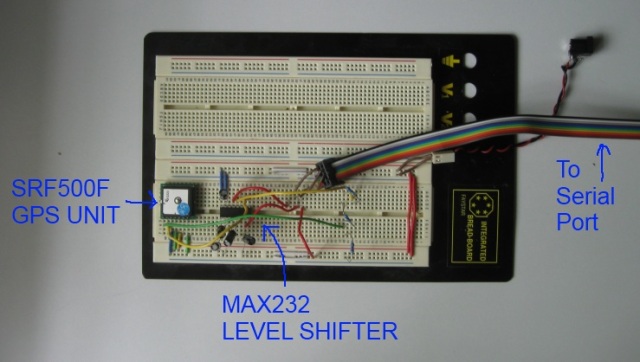
Here it is on the breadboard:

I’m using a MAX232 to convert the RS-232 voltages from the PCs serial port to TTL (5V), and a simple voltage divider to reduce the 5V TTL signal to the 3V required by the SRF500F’s UART. Continue reading

Posted in GPS | Tagged | 1 Comment